
Arduino Ultrasonic Distance Meter Using LCD and 6 LEDs
Introduction
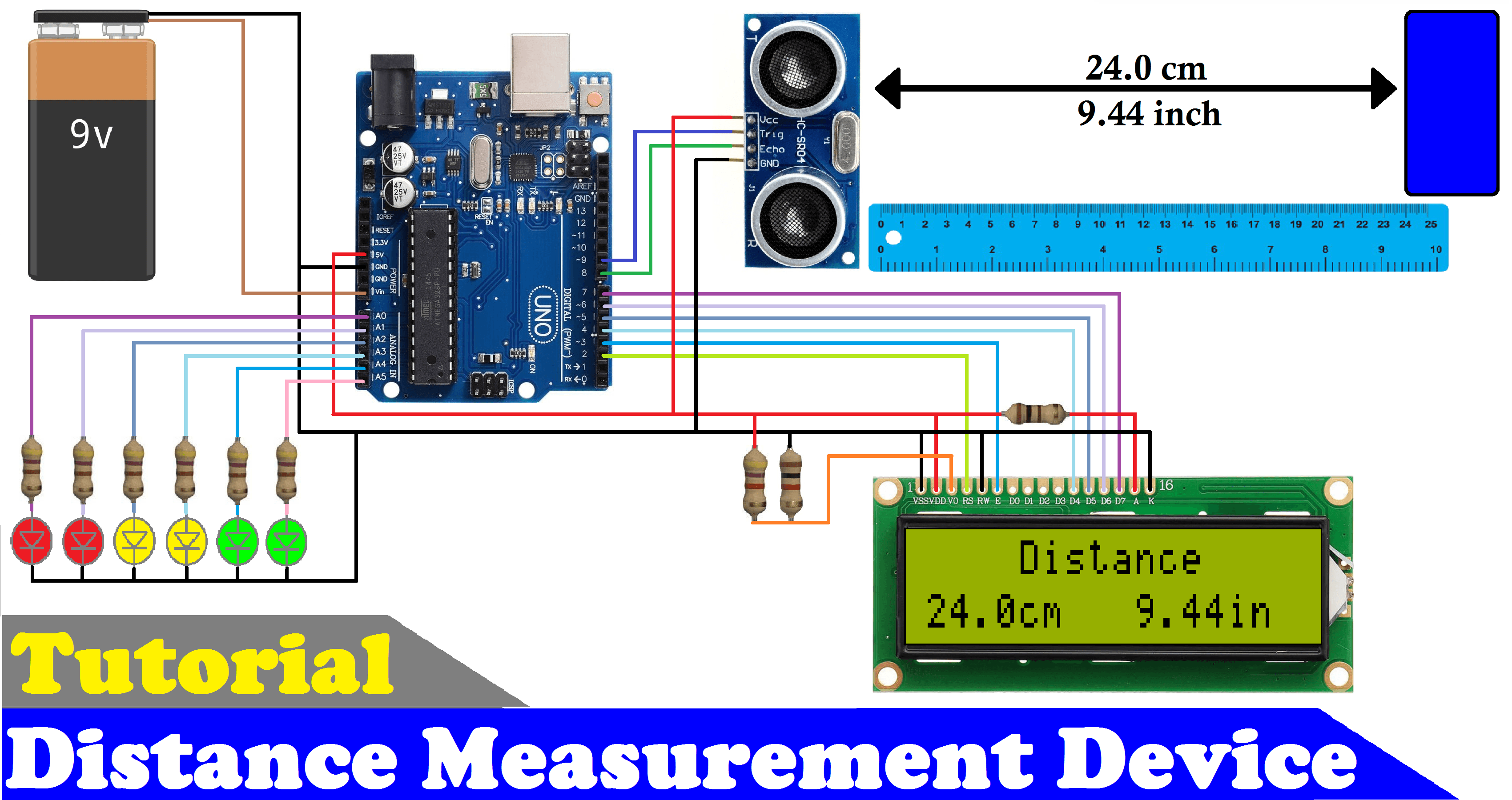
An Arduino Ultrasonic Distance Meter measures the distance between a sensor and a nearby object using ultrasonic sound waves. This project uses an HC-SR04 ultrasonic sensor, a 16x2 LCD, and six LEDs to display distance readings and indicate how close an object is.
The LCD displays the measured distance in centimeters and inches. The six LEDs illuminate at different distance thresholds, making the device useful for demonstrating proximity detection and distance-based visual alerts.
This beginner-friendly project introduces ultrasonic sensing, LCD interfacing, analog-free digital sensor communication, and conditional programming with Arduino.
Project Objectives
- Measure the distance to nearby objects using an ultrasonic sensor.
- Display distance in centimeters and inches.
- Show distance readings on a 16x2 LCD.
- Use six LEDs to indicate different distance thresholds.
- Print measurements to the Arduino Serial Monitor.
- Learn how Arduino interacts with sensors and output devices.
Components Required
| Component | Quantity |
|---|---|
| Arduino Uno | 1 |
| HC-SR04 ultrasonic sensor | 1 |
| 16x2 LCD display | 1 |
| Red LEDs | 2 |
| Yellow LEDs | 2 |
| Green LEDs | 2 |
| Current-limiting resistors for LEDs | 6 |
| 10 kΩ potentiometer for LCD contrast | 1 |
| Breadboard | 1 |
| Jumper wires | As required |
| USB cable or suitable power supply | 1 |
Circuit Diagram
Place the circuit diagram here to show the Arduino, HC-SR04 sensor, LCD, and six LEDs.

Circuit Connections
HC-SR04 Ultrasonic Sensor
| HC-SR04 Pin | Arduino Pin |
|---|---|
| VCC | 5V |
| GND | GND |
| TRIG | Digital pin 9 |
| ECHO | Digital pin 8 |
16x2 LCD in 4-Bit Mode
| LCD Pin | Arduino Pin |
|---|---|
| RS | Digital pin 2 |
| E | Digital pin 3 |
| D4 | Digital pin 4 |
| D5 | Digital pin 5 |
| D6 | Digital pin 6 |
| D7 | Digital pin 7 |
| VSS | GND |
| VDD | 5V |
| VO | Potentiometer middle pin |
| RW | GND |
| LED+ | 5V, with suitable current limiting if required |
| LED- | GND |
Connect the potentiometer's outer pins to 5V and GND to adjust LCD contrast.
Six LED Indicators
| LED | Arduino Pin | Color | Activation Threshold |
|---|---|---|---|
| LED 1 | A0 | Red | Below 10 cm |
| LED 2 | A1 | Red | Below 20 cm |
| LED 3 | A2 | Yellow | Below 30 cm |
| LED 4 | A3 | Yellow | Below 40 cm |
| LED 5 | A4 | Green | Below 50 cm |
| LED 6 | A5 | Green | Below 60 cm |
Connect each LED through an appropriate current-limiting resistor, such as 220–330 Ω. The LEDs share the Arduino's GND reference.
How the Project Works
- The Arduino sends a short trigger pulse to the HC-SR04 sensor.
- The sensor transmits an ultrasonic wave and receives its echo after it reflects from an object.
- Arduino measures the duration of the ECHO pulse.
- The program calculates the distance in centimeters and inches.
- The LCD displays both measurements.
- The Serial Monitor prints the distance readings.
- The six LEDs turn on or off according to their distance thresholds.
- As an object moves closer, more LEDs illuminate.
LED behavior: The thresholds are cumulative. For example, at a distance of 15 cm, LED 2 and LEDs 3–6 turn on, while LED 1 remains off. At a distance below 10 cm, all six LEDs turn on.
Arduino Source Code
#include <LiquidCrystal.h>

// LCD connections: RS, E, D4, D5, D6, D7
LiquidCrystal lcd(2, 3, 4, 5, 6, 7);

#define echoPin 8
#define trigPin 9

#define led1 A0
#define led2 A1
#define led3 A2
#define led4 A3
#define led5 A4
#define led6 A5

float time;
float distance_cm;
float distance_in;

void setup() {
  Serial.begin(9600);

  pinMode(trigPin, OUTPUT);
  pinMode(echoPin, INPUT);

  pinMode(led1, OUTPUT);
  pinMode(led2, OUTPUT);
  pinMode(led3, OUTPUT);
  pinMode(led4, OUTPUT);
  pinMode(led5, OUTPUT);
  pinMode(led6, OUTPUT);

  lcd.begin(16, 2);

  lcd.setCursor(0, 0);
  lcd.print(" Welcome To My ");

  lcd.setCursor(0, 1);
  lcd.print("YouTube Channel");

  delay(1000);
  lcd.clear();
}

void loop() {
  // Trigger the ultrasonic sensor
  digitalWrite(trigPin, LOW);
  delayMicroseconds(2);

  digitalWrite(trigPin, HIGH);
  delayMicroseconds(10);
  digitalWrite(trigPin, LOW);

  // Measure echo duration
  time = pulseIn(echoPin, HIGH);

  // Calculate distance
  distance_cm = (time / 2) / 29.1;
  distance_in = (time / 2) / 73.914;

  // Display distance on LCD
  lcd.setCursor(0, 0);
  lcd.print("    Distance    ");

  lcd.setCursor(0, 1);
  lcd.print(distance_cm, 1);
  lcd.print("cm  ");

  lcd.setCursor(9, 1);
  lcd.print(distance_in, 1);
  lcd.print("in  ");

  // Print distance to Serial Monitor
  Serial.print("cm= ");
  Serial.print(distance_cm);
  Serial.print(" inch= ");
  Serial.println(distance_in);

  // Control LEDs based on distance
  digitalWrite(led6, distance_cm < 60);
  digitalWrite(led5, distance_cm < 50);
  digitalWrite(led4, distance_cm < 40);
  digitalWrite(led3, distance_cm < 30);
  digitalWrite(led2, distance_cm < 20);
  digitalWrite(led1, distance_cm < 10);

  delay(200);
}
Code Explanation
1. LCD Initialization
LiquidCrystal lcd(2, 3, 4, 5, 6, 7);
lcd.begin(16, 2);
The LiquidCrystal library controls the 16-column, 2-row LCD. The constructor defines the six Arduino connections used for LCD communication.
2. Triggering the Ultrasonic Sensor
digitalWrite(trigPin, LOW);
delayMicroseconds(2);
digitalWrite(trigPin, HIGH);
delayMicroseconds(10);
digitalWrite(trigPin, LOW);
The Arduino sends a 10-microsecond trigger pulse to initiate a distance measurement.
3. Measuring Echo Duration
time = pulseIn(echoPin, HIGH);
The pulseIn() function measures how long the ECHO signal stays HIGH. This represents the ultrasonic wave's round-trip travel time.
4. Calculating Distance
distance_cm = (time / 2) / 29.1;
distance_in = (time / 2) / 73.914;
The calculation divides the travel time by two because the sound travels to the object and back. The constants approximate the speed of sound for conversions into centimeters and inches.
5. Displaying Measurements
lcd.print(distance_cm, 1);
lcd.print("cm");
The second argument 1 displays one digit after the decimal point. The LCD presents the centimeter and inch readings.
6. Controlling the LEDs
digitalWrite(led1, distance_cm < 10);
When the measured distance is below 10 cm, LED 1 turns on. Each remaining LED uses a higher threshold. This creates a cumulative visual indication of proximity.
Implementation Steps
- Assemble the LCD circuit according to the connection table.
- Connect the HC-SR04 sensor's TRIG and ECHO pins to Arduino pins 9 and 8.
- Connect the six LEDs to A0–A5 through current-limiting resistors.
- Connect all component grounds to Arduino GND.
- Open Arduino IDE and select the Arduino Uno board and correct port.
- Upload the code.
- Open the Serial Monitor and set its baud rate to 9600.
- Place an object in front of the sensor.
- Move the object closer and farther away.
- Observe the LCD measurements and the LED indicators.
Expected Output
| Object Distance | LEDs Expected to Be ON |
|---|---|
| 55 cm | LED 6 |
| 45 cm | LEDs 5–6 |
| 35 cm | LEDs 4–6 |
| 25 cm | LEDs 3–6 |
| 15 cm | LEDs 2–6 |
| 5 cm | LEDs 1–6 |
| 60 cm or more | All LEDs OFF |
These examples assume the sensor is returning valid measurements and the distance falls within its practical operating range.
Troubleshooting
LCD displays no text
- Check the LCD's power and GND connections.
- Adjust the contrast potentiometer.
- Verify the RS, E, and D4–D7 connections.
- Confirm the correct LCD pin order in
LiquidCrystal lcd(...).
Distance readings are incorrect
- Verify the TRIG and ECHO wiring.
- Keep the object facing the sensor.
- Avoid soft or angled surfaces that may absorb or deflect sound.
- Check the sensor's power supply and measurement range.
LEDs do not turn on
- Verify LED polarity.
- Check the resistor and wiring connections.
- Confirm that each LED is connected to the intended Arduino pin.
LCD readings leave old characters on the screen
- Print enough trailing spaces to overwrite old values.
- Keep the displayed measurements within the available 16-character row width.
Distance shows zero when no object is detected
pulseIn()can return zero if no echo is received within its timeout. The original code does not specify a timeout, so it may wait for a relatively long time. A more robust version should use a timeout and handle missing echoes separately.
Applications
- Parking assistance prototypes.
- Object proximity indicators.
- Robotics and obstacle-detection demonstrations.
- Distance measurement experiments.
- Electronics and embedded systems laboratory projects.
- Educational demonstrations of sensor-based automation.
Advantages
- Low-cost and beginner-friendly.
- Displays distance in two units.
- Provides visual feedback through six LEDs.
- Demonstrates real-time sensor readings.
- Can be expanded into more advanced automation systems.
Limitations
- Ultrasonic measurements can vary with object shape, surface, and angle.
- The six LED thresholds provide only approximate proximity levels.
- The original code does not explicitly handle missing echoes.
- The LCD and sensor require careful wiring and power connections.
- The project does not include wireless connectivity or remote monitoring.
Future Improvements
- Add a buzzer to warn when an object is very close.
- Use a bar-style indicator or change the LED logic to light only one LED at a time.
- Add an ESP32 for wireless monitoring.
- Record distance measurements for analysis.
- Add timeout handling and filtering to improve measurement stability.
- Use a larger LCD or OLED display for additional information.
Conclusion
The Arduino Ultrasonic Distance Meter is a practical beginner electronics project that combines distance measurement, LCD output, and LED indicators. It helps learners understand how ultrasonic sensors work and how Arduino can use sensor readings to control multiple outputs.
The same concepts can be applied to parking assistants, robotics, obstacle detection, and other proximity-based automation projects.