
Arduino Servo Motor Control: 5 Practical Code Examples
Introduction
A servo motor is an actuator that can move to a specific angular position. Unlike a basic DC motor, a standard positional servo can be instructed to move to an angle such as 0°, 90°, or 180°.
In this project, you will learn several ways to control a servo motor using Arduino. Each example builds on the same basic idea, from automatic sweeping to manual control and sensor-based movement.
Components Required
| Component | Quantity |
|---|---|
| Arduino Uno | 1 |
| SG90 or compatible positional servo | 1 |
| Breadboard | 1 |
| Jumper wires | As required |
| 10 kΩ potentiometer | 1 |
| Push buttons | 2 |
| HC-SR04 ultrasonic sensor | 1 |
| USB cable or suitable power supply | 1 |
You only need the components mentioned in the particular example you choose to build.
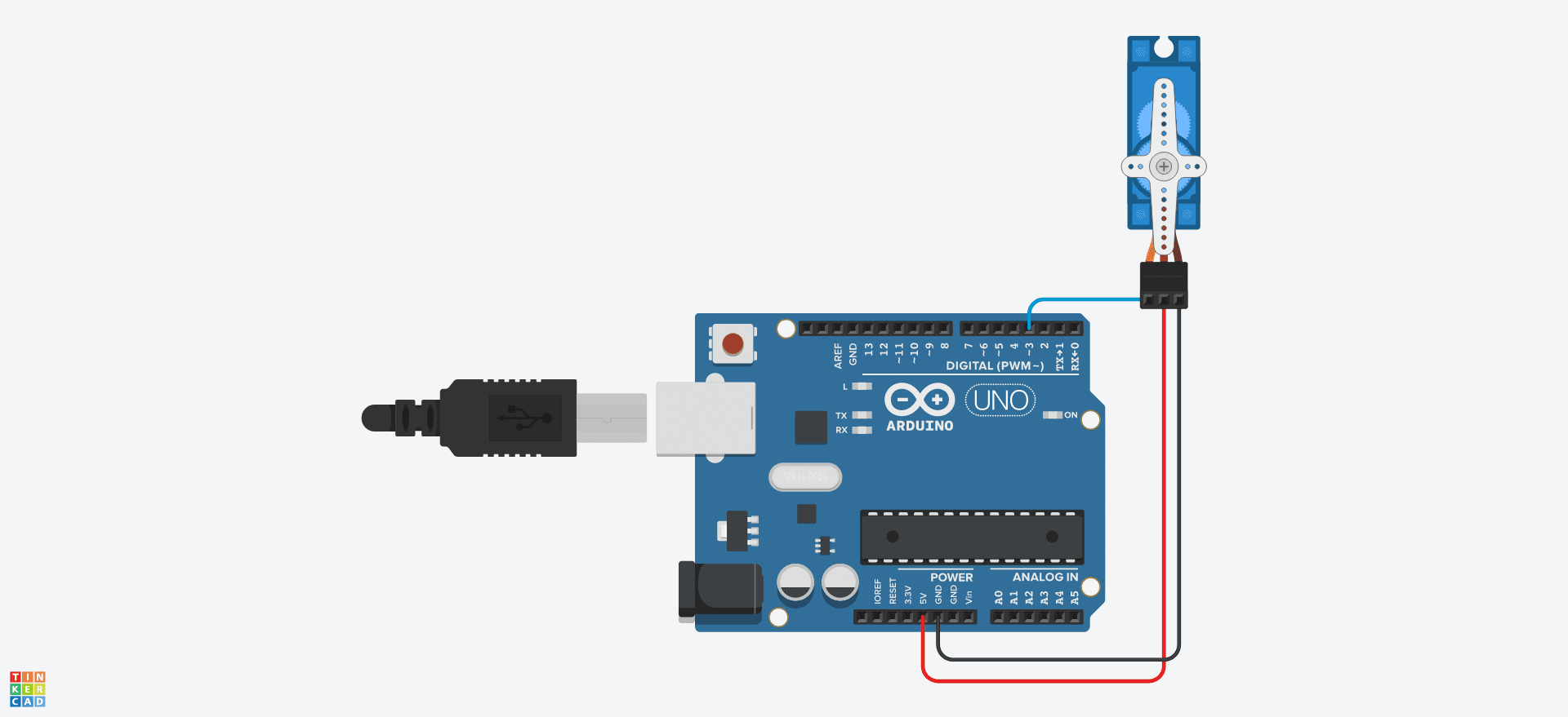
Circuit Connections
Servo Motor
| Servo Wire | Arduino Connection |
|---|---|
| Signal, usually orange or yellow | Digital pin 3 |
| VCC, usually red | Suitable supply voltage |
| GND, usually brown or black | GND |
For a small servo, a suitable external regulated supply may be necessary. Connect the external supply's GND to Arduino GND. Check the servo's voltage and current requirements before connecting it.
Example 1: Automatic Servo Sweep (0° to 180°)
This example continuously moves the servo from 0° to 180° and then returns it to 0°.
Code
#include <Servo.h>

Servo servo;

void setup() {
  servo.attach(3);
}

void loop() {
  // Move from 0 to 180 degrees
  for (int i = 0; i <= 180; i++) {
    servo.write(i);
    delay(50);
  }

  // Move from 180 back to 0 degrees
  for (int i = 180; i >= 0; i--) {
    servo.write(i);
    delay(50);
  }
}
Working Principle
servo.attach(3)assigns pin 3 as the servo signal pin.servo.write(i)requests a position in degrees.- The first
forloop increases the angle from 0° to 180°. - The second loop decreases the angle from 180° to 0°.
delay(50)controls the interval between angle commands.
Expected result: The servo moves smoothly back and forth, taking approximately nine seconds for a complete round trip with these delays.
Example 2: Move the Servo to Fixed Positions
This example moves the servo between three positions: 0°, 90°, and 180°.
Code
#include <Servo.h>

Servo servo;

void setup() {
  servo.attach(3);
}

void loop() {
  servo.write(0);
  delay(1000);

  servo.write(90);
  delay(1000);

  servo.write(180);
  delay(1000);
}
Working Principle
The servo moves to each requested angle and waits one second before receiving the next position command.
Expected result: The servo pauses at each of the three positions before repeating the sequence.
Applications: Miniature gates, rotating displays, and simple position-control demonstrations.
Example 3: Control Servo Position Using a Potentiometer
In this example, a potentiometer controls the servo angle. Turning the knob changes the angle between 0° and 180°.
Additional Connection
| Component | Arduino Connection |
|---|---|
| Potentiometer outer pin 1 | 5V |
| Potentiometer outer pin 2 | GND |
| Potentiometer middle pin | A0 |
| Servo signal | Digital pin 3 |
Code
#include <Servo.h>

Servo servo;

const int potPin = A0;
int sensorValue;
int angle;

void setup() {
  servo.attach(3);
  Serial.begin(9600);
}

void loop() {
  sensorValue = analogRead(potPin);

  angle = map(sensorValue, 0, 1023, 0, 180);

  servo.write(angle);

  Serial.print("Potentiometer: ");
  Serial.print(sensorValue);
  Serial.print(" | Servo angle: ");
  Serial.println(angle);

  delay(15);
}
Working Principle
- Arduino reads the potentiometer through A0.
analogRead()produces a value from 0 to 1023.map()converts that value into an angle from 0° to 180°.- The servo moves to the calculated angle.
Expected result: Turning the potentiometer changes the servo position.
Example 4: Control Servo Position Using Two Push Buttons
This example uses two push buttons to move the servo in small steps. One button decreases the angle, while the other increases it.
Additional Connections
| Component | Arduino Connection |
|---|---|
| Increase button | Pin 4 and GND |
| Decrease button | Pin 5 and GND |
| Servo signal | Digital pin 3 |
The buttons use Arduino's internal pull-up resistors, so each button should connect its input pin to GND when pressed.
Code
#include <Servo.h>

Servo servo;

const int increaseButton = 4;
const int decreaseButton = 5;

int angle = 90;

void setup() {
  servo.attach(3);

  pinMode(increaseButton, INPUT_PULLUP);
  pinMode(decreaseButton, INPUT_PULLUP);

  servo.write(angle);
}

void loop() {
  if (digitalRead(increaseButton) == LOW) {
    angle += 5;

    if (angle > 180) {
      angle = 180;
    }

    servo.write(angle);
    delay(200);
  }

  if (digitalRead(decreaseButton) == LOW) {
    angle -= 5;

    if (angle < 0) {
      angle = 0;
    }

    servo.write(angle);
    delay(200);
  }
}
Working Principle
- The servo starts at 90°.
- Pressing the increase button adds 5°.
- Pressing the decrease button subtracts 5°.
- The angle is restricted to the range 0°–180°.
- A short delay helps reduce repeated changes while a button is held, though proper debouncing can improve the design further.
Expected result: The buttons move the servo step by step.
Example 5: Automatic Servo Movement Using an Ultrasonic Sensor
This example moves the servo according to the distance measured by an HC-SR04 ultrasonic sensor. When an object comes closer than 15 cm, the servo moves to 90°. Otherwise, it returns to 0°.
Additional Connections
| HC-SR04 Pin | Arduino Pin |
|---|---|
| VCC | 5V |
| GND | GND |
| TRIG | 9 |
| ECHO | 8 |
Keep the servo signal on pin 3.
Code
#include <Servo.h>

Servo servo;

const int trigPin = 9;
const int echoPin = 8;

long duration;
float distanceCm;

void setup() {
  Serial.begin(9600);

  servo.attach(3);

  pinMode(trigPin, OUTPUT);
  pinMode(echoPin, INPUT);

  servo.write(0);
}

void loop() {
  digitalWrite(trigPin, LOW);
  delayMicroseconds(2);

  digitalWrite(trigPin, HIGH);
  delayMicroseconds(10);
  digitalWrite(trigPin, LOW);

  duration = pulseIn(echoPin, HIGH, 30000);

  if (duration == 0) {
    Serial.println("No echo detected");
    delay(100);
    return;
  }

  distanceCm = duration * 0.0343 / 2;

  Serial.print("Distance: ");
  Serial.print(distanceCm);
  Serial.println(" cm");

  if (distanceCm < 15) {
    servo.write(90);
  } else {
    servo.write(0);
  }

  delay(100);
}
Working Principle
- The ultrasonic sensor measures the distance to an object.
- Arduino calculates the distance using the ECHO pulse duration.
- If the distance is below 15 cm, the servo moves to 90°.
- Otherwise, the servo moves to 0°.
- If no echo is received, the program leaves the servo at its previous position.
Expected result: Bringing an object close to the sensor changes the servo position.
Applications: Automatic barriers, touch-free demonstrations, and simple proximity-controlled mechanisms.
Troubleshooting
Servo does not move
- Check the signal connection and servo power.
- Verify that the servo is compatible with the supply voltage.
- Make sure the Arduino and external servo supply share GND.
Arduino resets when the servo moves
- The servo may draw more current than the Arduino can provide.
- Use a suitable regulated external supply.
- Check for loose ground connections.
Servo makes noise or vibrates
- Check the mechanical load and power supply.
- Ensure the servo is not being forced beyond its physical range.
- Use a suitable servo model for the required load.
Potentiometer control is reversed
- Swap the potentiometer's two outer connections or reverse the output range in
map().
Ultrasonic example gives inconsistent results
- Verify the TRIG and ECHO wiring.
- Keep the object facing the sensor.
- Avoid soft or angled surfaces that may absorb or deflect sound.
Applications
- Automatic gate and barrier prototypes.
- Robotics and simple joint-position demonstrations.
- Potentiometer-controlled mechanisms.
- Sensor-based automation.
- Educational electronics and embedded systems projects.
Future Improvements
- Add an LCD or OLED to display the servo angle.
- Add an ESP32 for wireless control.
- Create a web-based servo control panel.
- Add smoother movement using smaller steps and timing control.
- Add limit switches for mechanisms that need physical position feedback.
Conclusion
Servo motors are useful for projects that require controlled angular movement. These five examples demonstrate how Arduino can control a servo using timed movement, fixed angles, a potentiometer, push buttons, and an ultrasonic sensor.
Start with the automatic sweep example, then progress to manual and sensor-based control. These techniques provide a foundation for building more advanced robotics and IoT projects.